ATTiny Minibadge Devboard
An ATtiny816/1616 on a SAINTCON Minibadge, full of I/O for USART, SPI, I2C, and more!
R3 Devboard Minibadges
Introduction
What is it?
An ATtiny 816/1616 on a SAINTCON Minibadge, crammed full of breakout pins for I2C, USART, SPI, DAC, ADC, and PTC. It is also hooked up to the I2C lines on the Minibadge standard, so you can use the microcontroller to talk to the main SAINTCON Minibadge, if you know what you want to say to it.
Why did you make it?
I wanted to level up my badge-making by incorporating some easy to use logic IC that doesn't break the bank, everything I've done up to this project has just been LEDs. This is my first project that has a programmable chip that can be flashed! This is meant to facilitate prototyping and development (especially minibadges) with the ATtiny series, as it's an incredibly cheap and moderately versatile chip.
A semi-complex Minibadge with an ATtiny and accessories/cheap sensors would still be probably less than $1.00/badge assembled.
Goals
What did you want to achieve?
- Cheap ($0.40~) IC with a small footprint and minimum supporting parts
- Design a Minibadge to help me understand how to use this chip on more Minibadges
- Hook up as much I/O as I could fit to facilitate maximum hardware interfaces and hacking
Design Process
What references and tools did you use?
- ATtiny816 Data Sheet
- AVR-Guidance repository by Spence Konde
- MegaTinyCore framework by Spence konde
- Arduino IDE
- Adafruit ATtiny816 Breakout
- Adafruit UPDI Friend
How did you design the circuit?
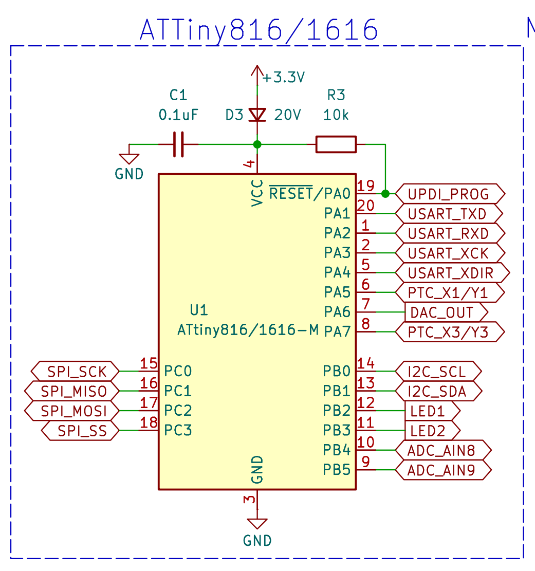
First, lets look at the schematic:
Basically, we've got 3 component sections. (we don't count the minibadge socket pin headers here)
- MCU
- LEDs
- Breakout connectors
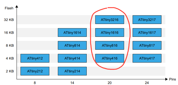
First, the MCU. I went with the ATtiny816(8KB flash, swappable for the ATtiny1616 - 16KB flash) The ATTiny only really requires a 10kΩ resistor tied from RESET (which is also the programming pin) to +3.3V, and a small 0.1μF capacitor to handle ripple.
All 20-pin ATtiny's in the WQFN-20 footprint would work in this board, but the 3216 is hard to come by for a good price, and the 416 is practically useless with only 4KB of flash.
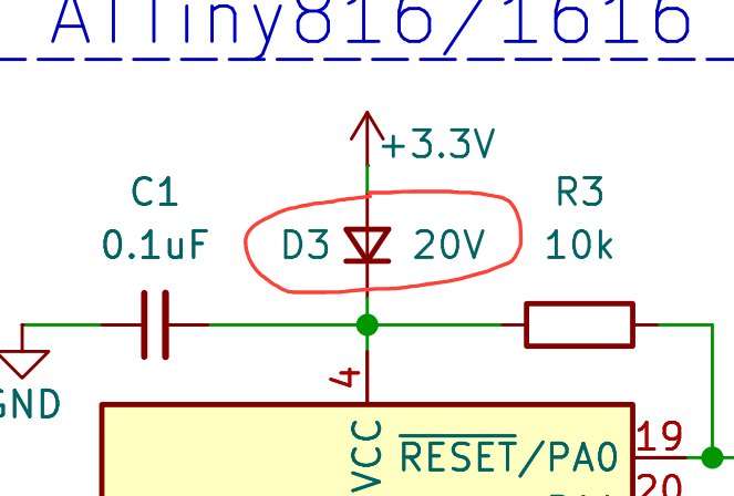
I later added a Schottky diode (D3) after reverse voltage failures due to plugging the minibadge in upside down. Reverse polarity protection is cheap, and I recommend throwing at least one protection on any board that has an MCU. I fried like 4 devboards figuring this out, and all boards before this revision are susceptible. If you get any of the boards before revision R6 and fry one accidently, I will replace it free of charge with a reverse-voltage protected R6+ board.
The LEDs are super simple, but no devboard is complete without at least one LED for debug and status indication. This is extra helpful as the ATtiny cannot do serial messages or any true debugging over UPDI, at least through the Arduino IDE. LEDs make it a lot easier to diagnose issues with code, especially when you don't have any other debug methods on this board. The LEDs are hooked up to two PWM-capable pins on the MCU, so they can have adjustable brightness and smooth dimming.
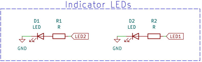
I threw two on there, since there were two pins left after everything else had been sorted out with the pinouts, discussed below.
After consulting the datasheet, specifically the Multiplexed Signals section (page 17), I was able to maximize the amount of fully-supported functions that could all be used at the same time, without switching pins in code.
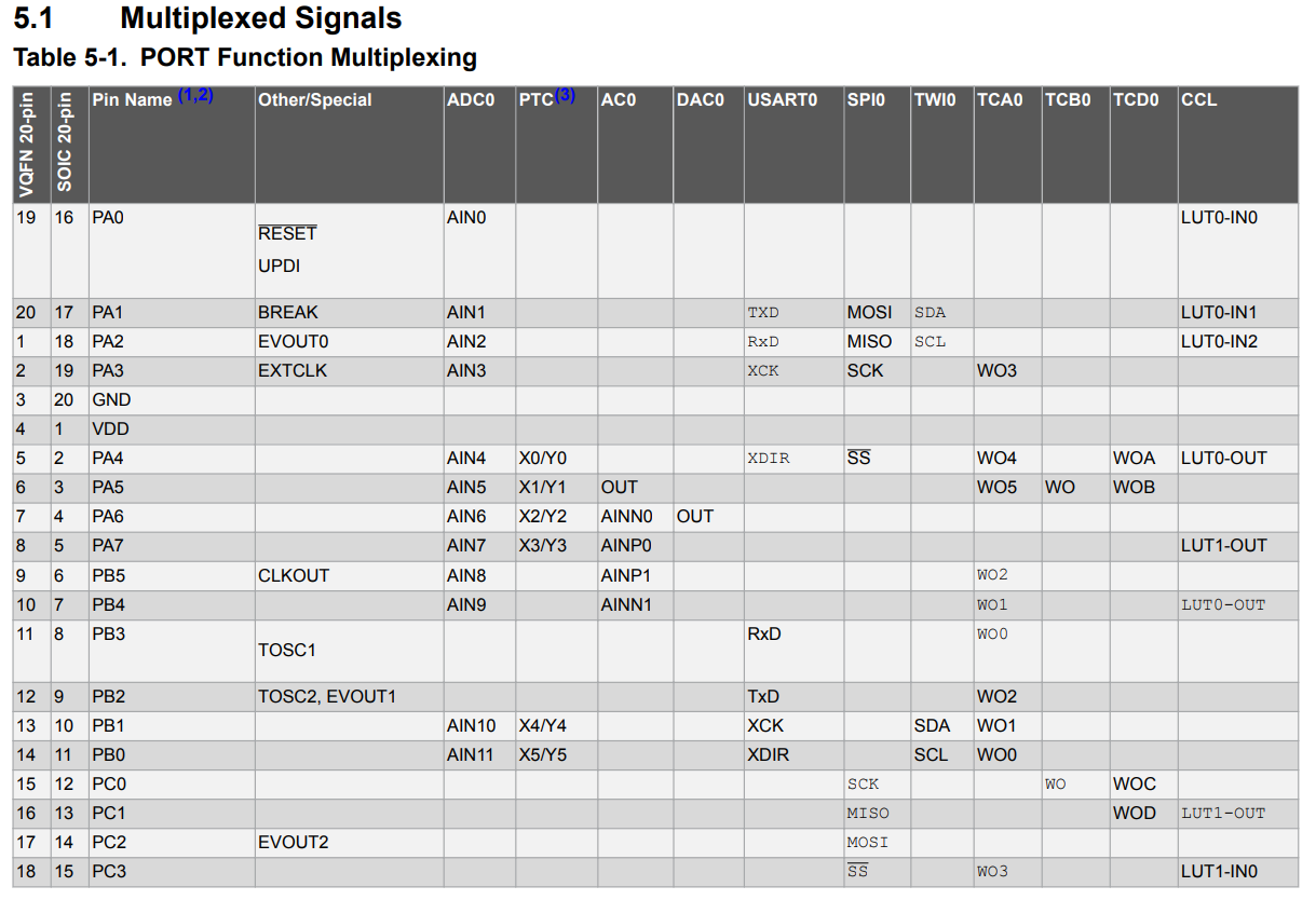
This means that you could (hopefully, haven't tested this lol) have accessories on I2C, USART, and SPI all at the same time and write code to interact will all systems synchronously.
Last, the breakout connectors. Now that we've figured out all of the possibly conflicting ports, it was easy-ish to lay out as they can all be dedicated to different interfaces without conflict, and they can all have their own special pinout.
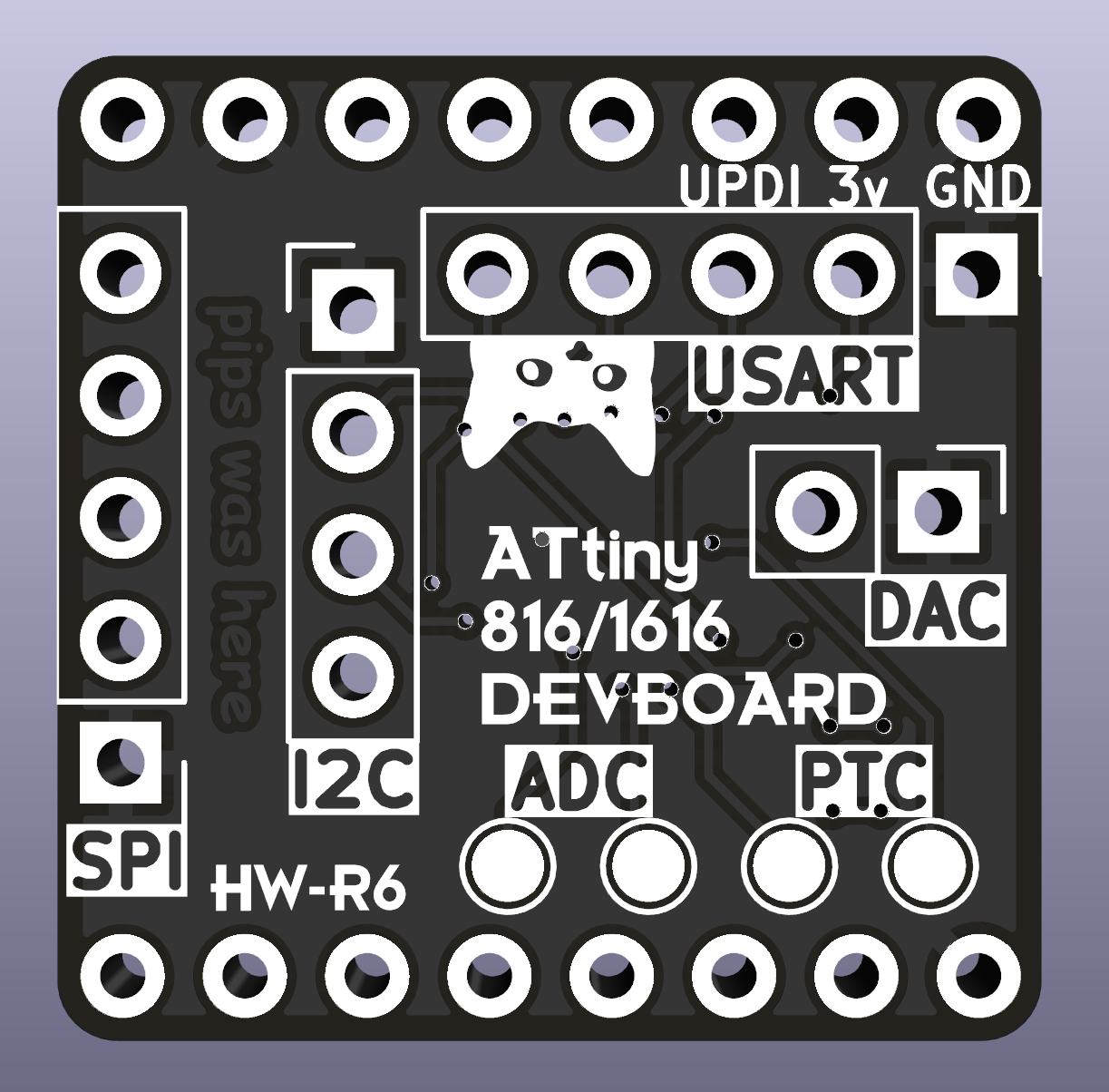
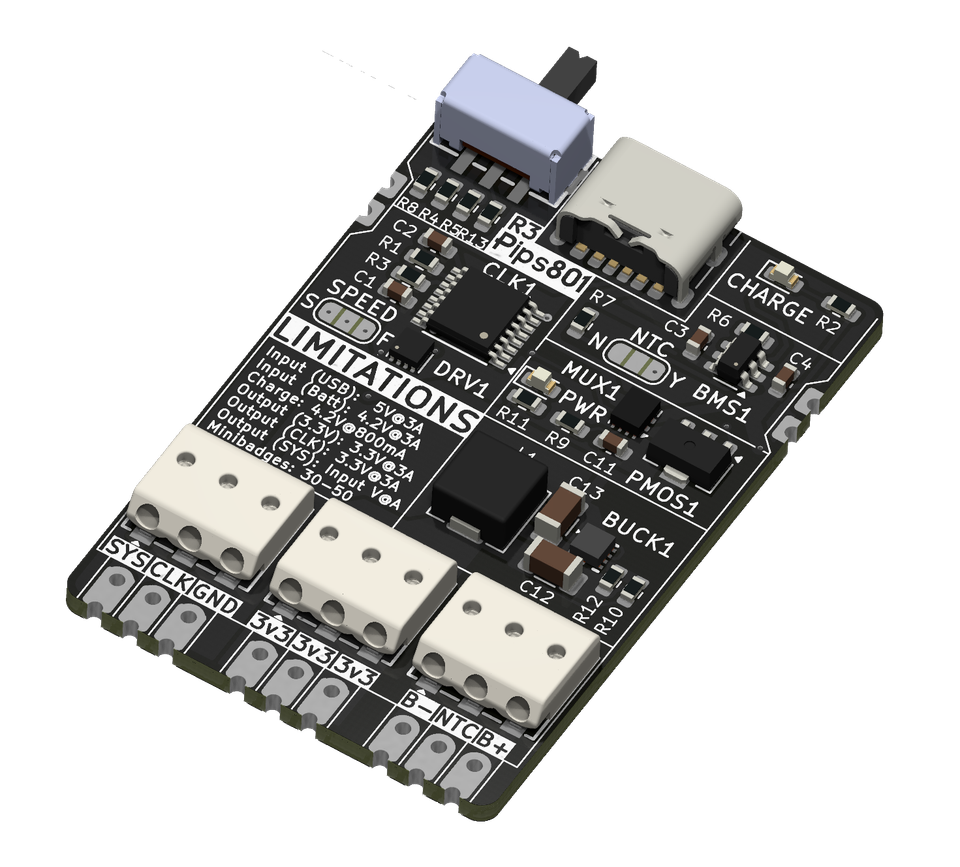
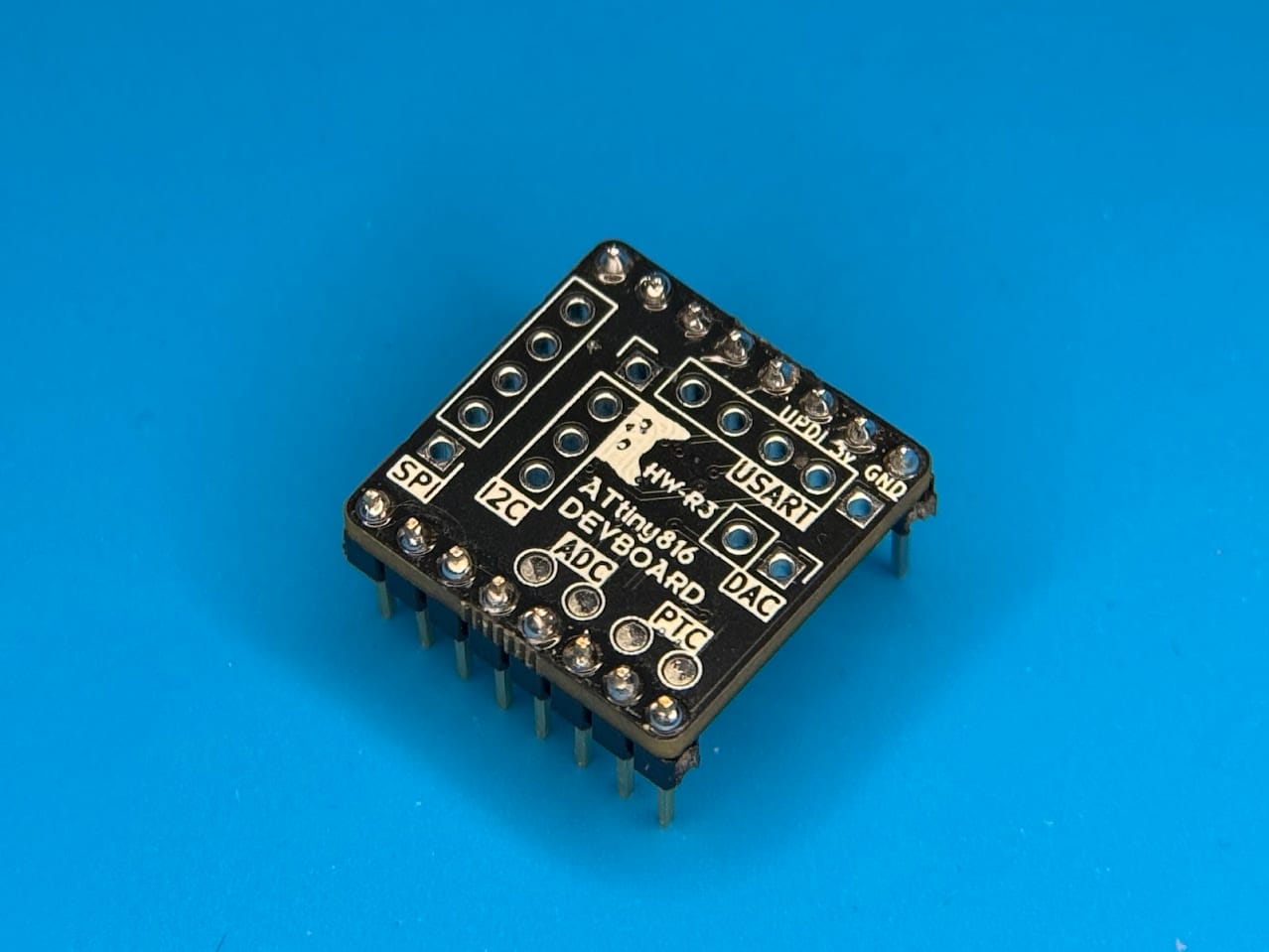
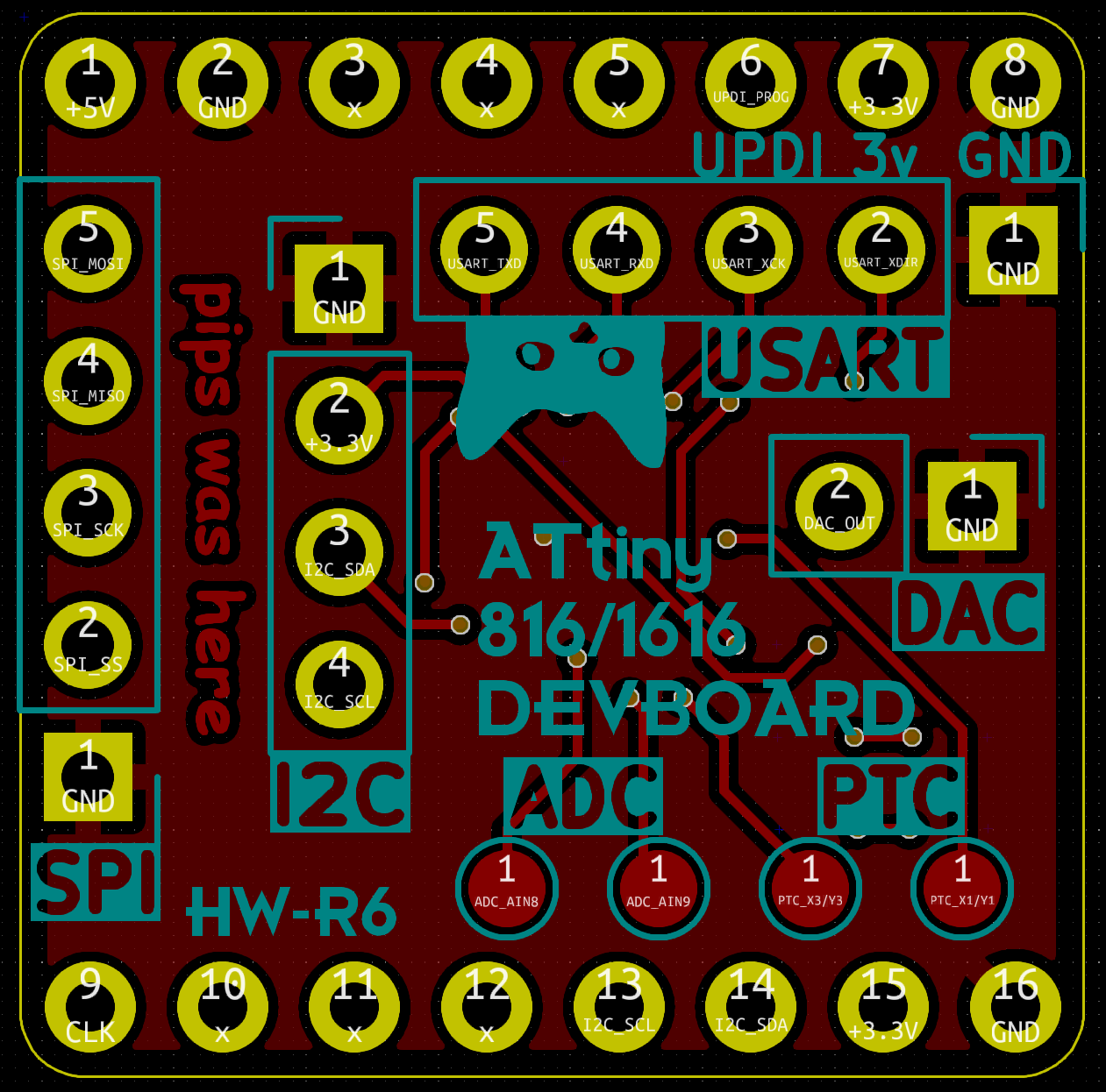
On the back of the minibadge, I have also labeled each pin for convenience. After consulting with @compukidmike, I added GND to each pinout, and labeled both 5v and CLK even though they are not connected to anything. I am super happy that my fab shop (JLCPCB) was able to do the silkscreen accurately enough to make out <0.8mm font text. The pins are very legible, even if the photo I took of them is bad.
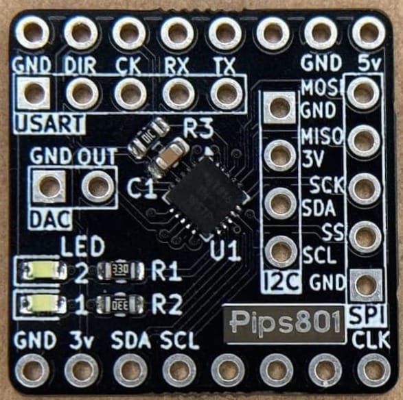
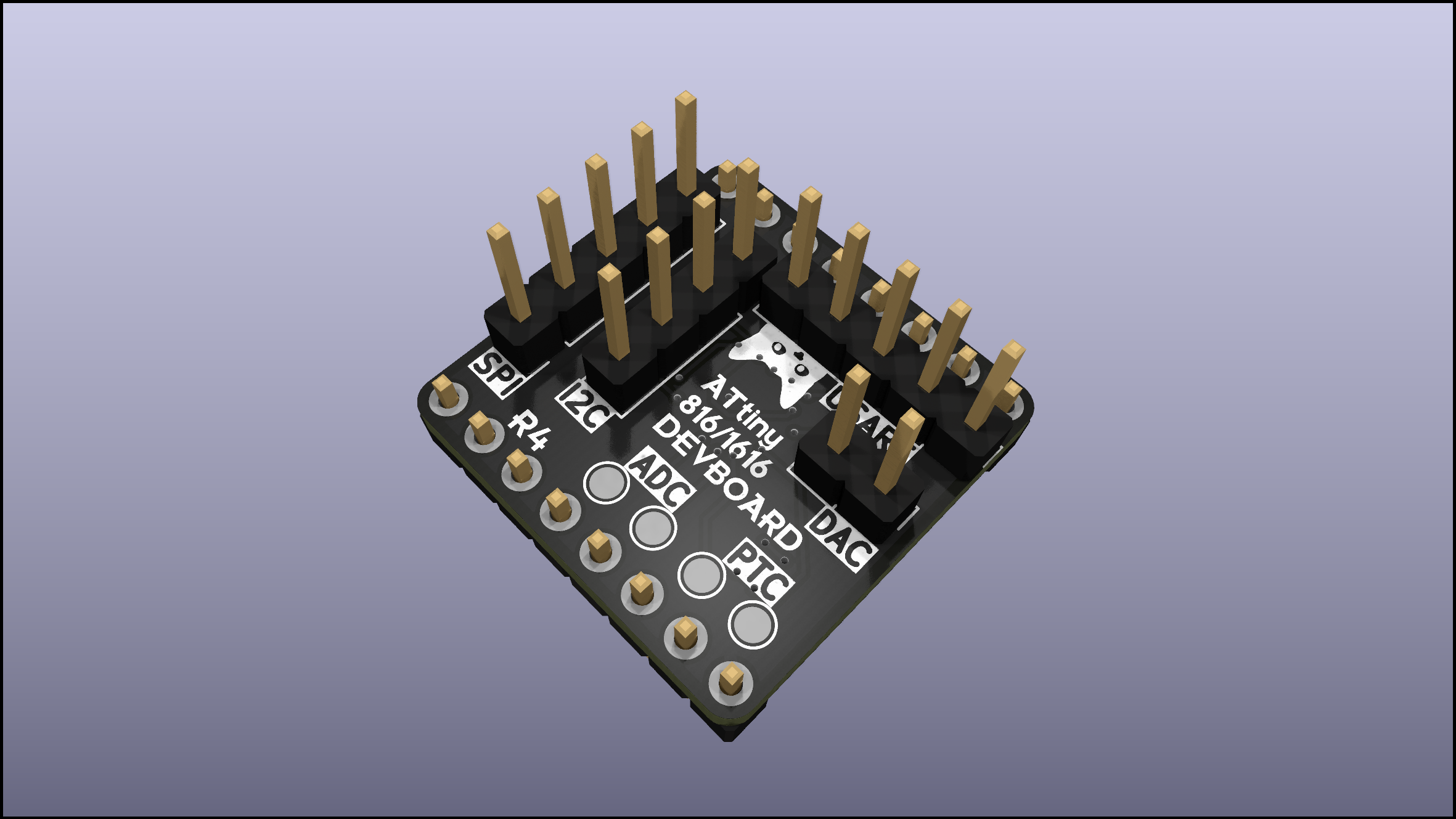
R6 Devboard 3D render showing pinouts (left) R3 Devboard photo showing silkscreen font resolution (right)
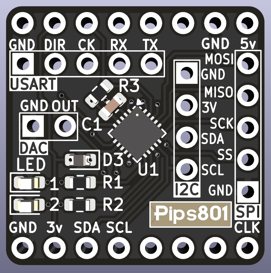
How did you design the board?
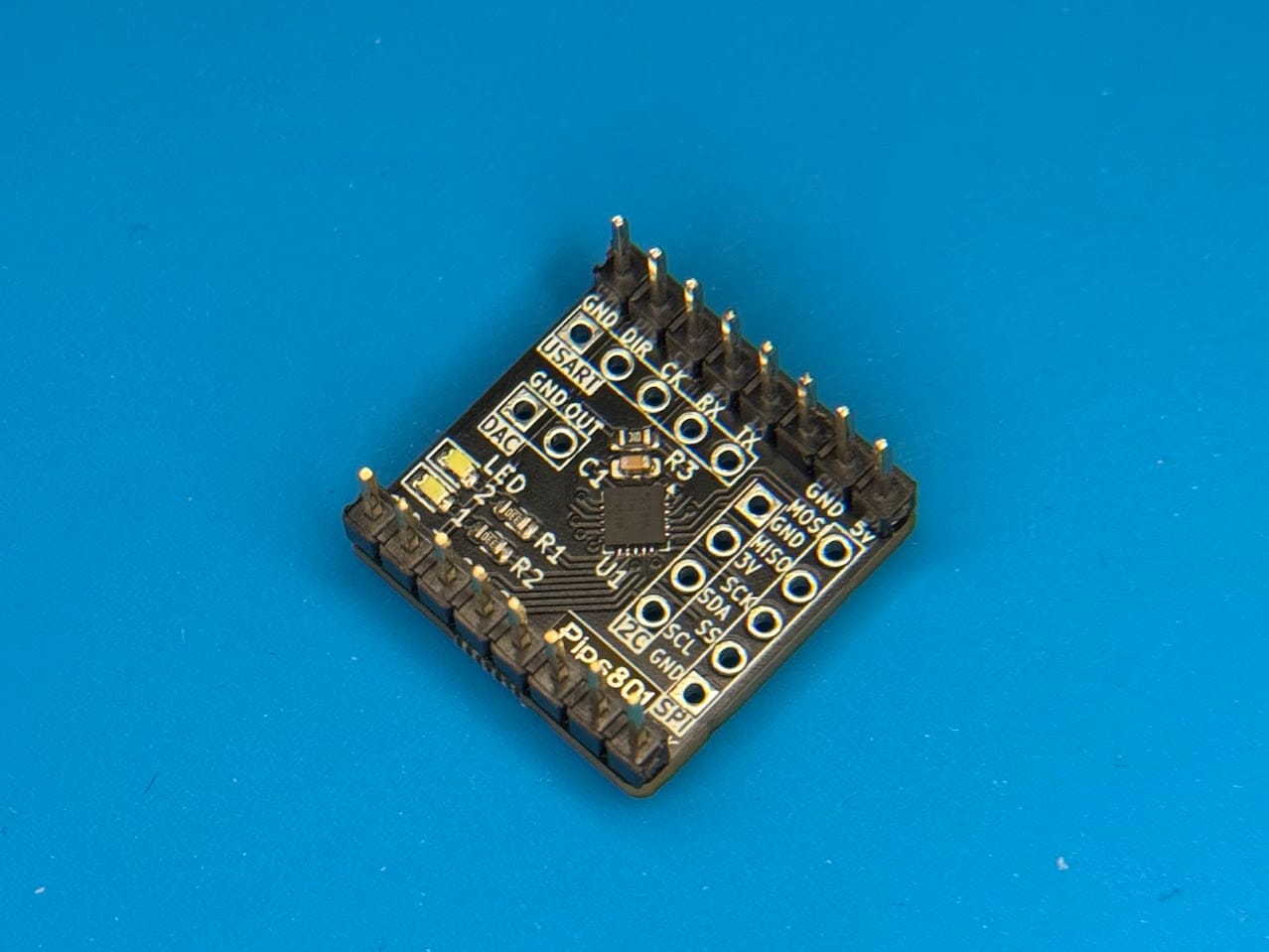
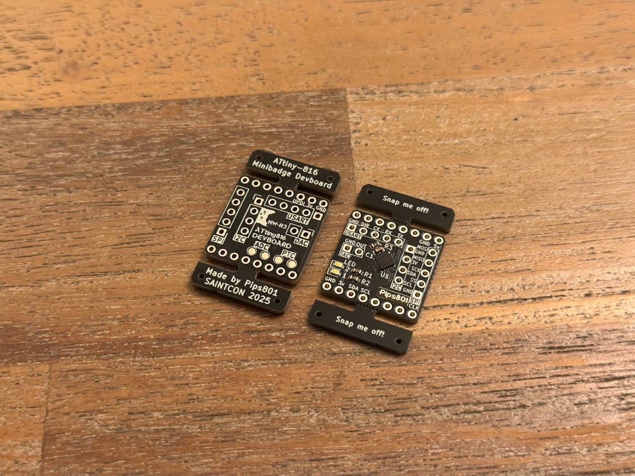
Lets look at the front and the back of the board:
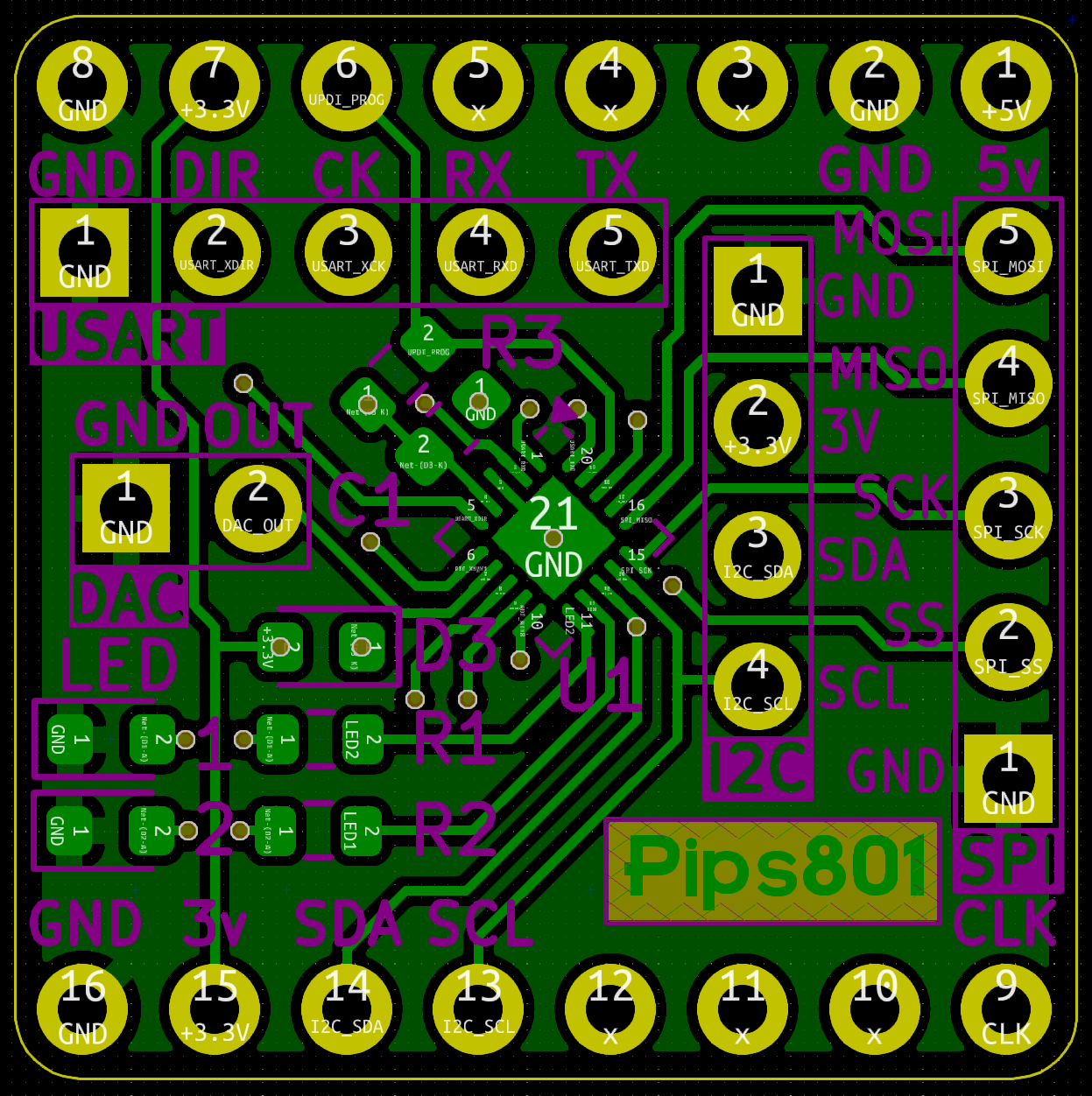
I decided to slap the MCU right dead center on the board, rotated 45 degrees. I thought it would look cool that way, with no real concern for how it would make routing. In some ways, being in the center of the board, it did make routing easier. When it came to supporting component placement, like R3 and C1, it made thigs a lot more difficult.
The front and back both have a ground plane, which made routing much easier as I only had to handle signals and power.
Writing software for the board
Morse code example
LED morse code blinking example code.
I2C example
The below example code makes the minibadge join an I2C bus as a client device, registering on the address 0x69. It will respond to a couple commands, and do a short blink for any command received but not understood. I was able to use this code in combination with this minibadge, a Flipper Zero, my Flipper Zero Minibadge Addon, and the I2C Tools Flipper Zero App.
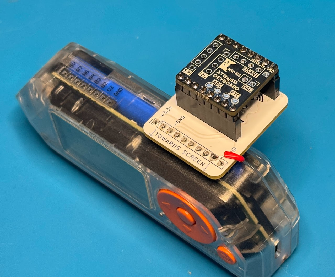

I2C Client example, will blink when it receives commands.
Programming the board
What do you need to program the board?
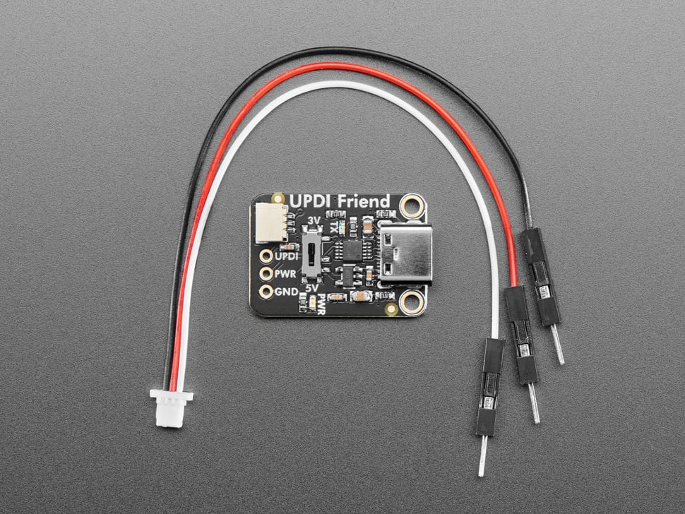
Since the chip is an ATtiny AVR1-series MCU, it only has one wire to program it over its UPDI port. You will need a UPDI programmer, I personally use the Adafruit UPDI Friend as it's quite cost-effective, but there are many other options out there.
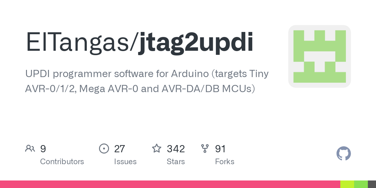
You can also turn a spare Arduino into a UPDI programmer using JTAG2UPDI
Or you could acquire one of the many cool AVR-Programmers that @wagiminator has created. They're for sale on OSHWlab!
There are many other cool USB to UPDI projects out there, like this one.
What do you have to do to program the board?
First, set up the Arduino IDE and add the MegaTinyCore board library to the IDE.
Once that's done, select the ATtiny 816 as your board. Under Tools -> Programmer select your programmer. Unless you splurged and bought Atmel-ICE hardware or some of the other full-suite debuggers, you will probably use SerialUPDI. Make sure to set it to the SLOW 57600 baud setting. Make sure to select the actual chip you have, either the Attiny816 or the Attiny1616. Be sure to change the clock to 10MHz Internal.
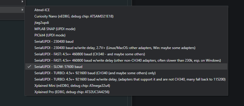
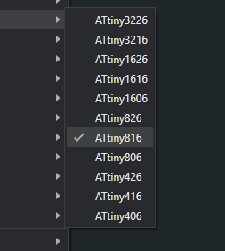
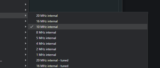
Use the SLOW baud rate, make sure to select your chip, and set your clock speed to 10MHz
With that done, you can now crank away and write and flash Arduino code! There are lots of examples, plenty are actually baked into the Arduino IDE itself.
Wrapping up the project
how do I get one?
You can purchase one on Tindie.com! Or, you can find me at SAINTCON 2025.
ATtiny 816/1616 Minibadge Devboard
An ATtiny 816/1616 on a SAINTCON Minibadge, crammed full of breakout pins for I2C, USART, SPI, DAC, ADC, and PTC
What would you iterate on further?
- I would love to swap the LEDs for RGB LEDs, which are much more capable of conveying a wider range of information to the end user.
- I must evaluate LEDs and LED control libraries to make an informed decision. Some ADC or PTC pins may go away to support one or more RGB LEDs.
- Throwing a small, cheap audio amplifier onto the DAC pins would enable direct audio output, though a low-voltage speaker/buzzer can still work.
- Directional indicators on the board, so the user has a better visual indicator of what direction to plug the minibadge in.
Wrapping up the post
What did you learn from this?
- Reverse voltage is not fun, and really easy to happen on a minibadge.
- I learned how to throw logic on a board for the first time. It's a really cool feeling to design the hardware, order it, and program it with code you wrote yourself.
- A lot about the ATtiny series and AVR chips.
What would you do different?
- Consider reverse voltage protections at the start of all projects. It costs almost nothing, and can save almost everything.
- Stick to a 2.54mm grid with the pinouts and make it much more devboard/perfboard-y. I am not a fan of the overall layout, and some symmetry would add extra usability, as well as look nicer.
- Consider JST to Dupont connectors to break out the board further, moving away from pin headers. This would be an increased cost and a full redesign.
How do you feel about your choices?
For a beginner, I am making good progress and ramping up the challenge and my ambitions.
I believe I made good choices when choosing this chip specifically, as it was at a price point of $0.45/ea and requires only one cap and resistor. It can do a lot of easy logic to enable user interaction, LED control, sensors, etc. This project is a stepping stone, and having this chip in my part inventory and under my toolbelt will open up the doors to more advanced projects.